EC2: Minimum shear reinforcement
9.2 Beams
9.2.2 Shear reinforcement
(1) The shear reinforcement should form an angle α of between 45º and 90º to the longitudinal axis of the structural element.
(2) The shear reinforcement may consist of a combination of:
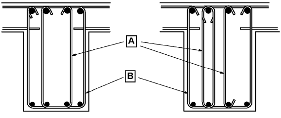
- links enclosing the longitudinal tension reinforcement and the compression zone (see Figure 9.5);
- bent-up bars;
- cages, ladders, etc. which are cast in without enclosing the longitudinal reinforcement but are properly anchored in the compression and tension zones.

A Inner link alternatives B Enclosing link
Figure 9.5: Examples of shear reinforcement
(3) Links should be effectively anchored. A lap joint on the leg near the surface of the web is permitted provided that the link is not required to resist torsion.
(4) At least β3 of the necessary shear reinforcement should be in the form of links.
Note: The value of β3 for use in a Country may be found in its National Annex. The recommended value is 0.5.
(5) The ratio of shear reinforcement is given by Expression (9.4):
where:
- ρw is the shear reinforcement ratio
- ρw should not be less than ρw,min
- Asw is the area of shear reinforcement within length s
- s is the spacing of the shear reinforcement measured along the longitudinal axis of the member
- bw is the breadth of the web of the member
- α is the angle between shear reinforcement and the longitudinal axis (see 9.2.2 (1))
Note: The value of ρw,min for beams for use in a Country may be found in its National Annex. The recommended value is given Expression (9.5N)
(6) The maximum longitudinal spacing between shear assemblies should not exceed sl,max:
Note: The value of sl,max for use in a Country may be found in its National Annex. The recommended value is given by Expression (9.6N)
where α is the inclination of the shear reinforcement to the longitudinal axis of the beam.
(7) The maximum longitudinal spacing of bent-up bars should not exceed sb,max:
Note: The value of sb,max for use in a Country may be found in its National Annex. The recommended value is given by Expression (9.7N)
(8) The transverse spacing of the legs in a series of shear links should not exceed st,max:
Note: The value of st,max for use in a Country may be found in its National Annex. The recommended value is given by Expression (9.8N)
9.5 Columns
9.5.3 Transverse reinforcement
(1) The diameter of the transverse reinforcement (links, loops or helical spiral reinforcement) should not be less than 6 mm or one quarter of the maximum diameter of the longitudinal bars, whichever is the greater. The diameter of the wires of welded mesh fabric for transverse reinforcement should not be less than 5 mm.
(2) The transverse reinforcement should be anchored adequately.
(3) The spacing of the transverse reinforcement along the column should not exceed scl,tmax
Note: The value of scl,tmax for use in a Country may be found in its National Annex. The recommended value is the least of the following three distances:
- 20 times the minimum diameter of the longitudinal bars
- the lesser dimension of the column
- 400 mm
(4) The maximum spacing required in (3) should be reduced by a factor 0,6:
- (i) in sections within a distance equal to the larger dimension of the column cross-section above or below a beam or slab;
- (ii) near lapped joints, if the maximum diameter of the longitudinal bars is greater than 14 mm. A minimum of 3 bars evenly placed in the lap length is required.
(5) Where the direction of the longitudinal bars changes, (e.g. at changes in column size), the spacing of transverse reinforcement should be calculated, taking account of the lateral forces involved. These effects may be ignored if the change of direction is less than or equal to 1 in 12.
(6) Every longitudinal bar or bundle of bars placed in a corner should be held by transverse reinforcement. No bar within a compression zone should be further than 150 mm from a restrained bar.


