EC2: Crack width and Stress limitation
7.2 Stress limitation
(1)P The compressive stress in the concrete shall be limited in order to avoid longitudinal cracks, micro-cracks or high levels of creep, where they could result in unacceptable effects on the function of the structure.
(2) Longitudinal cracks may occur if the stress level under the characteristic combination of loads exceeds a critical value. Such cracking may lead to a reduction of durability. In the absence of other measures, such as an increase in the cover to reinforcement in the compressive zone or confinement by transverse reinforcement, it may be appropriate to limit the compressive stress to a value k1·fck in areas exposed to environments of exposure classes XD, XF and XS (see Table 4.1).
Note: The value of k1 for use in a Country may be found in its National Annex. The recommended value is 0,6.
(4)P Tensile stresses in the reinforcement shall be limited in order to avoid inelastic strain, unacceptable cracking or deformation.
(5) For the appearance unacceptable cracking or deformation may be assumed to be avoided if, under the characteristic combination of loads, the tensile strength in the reinforcement does not exceed k3fyk. Where the stress is caused by an imposed deformation, the tensile strength should not exceed k4fyk. The mean value of the stress in prestressing tendons should not exceed k5fyk.
Note: The values of k3, k4 and k5 for use in a Country may be found in its National Annex. The recommended values are 0,8, 1 and 0,75 respectively.
7.3 Crack control
7.3.1 General considerations
(1)P Cracking shall be limited to an extent that will not impair the proper functioning or durability of the structure or cause its appearance to be unacceptable.
(2) Cracking is normal in reinforced concrete structures subject to bending, shear, torsion or tension resulting from either direct loading or restraint or imposed deformations.
(3) Cracks may also arise from other causes such as plastic shrinkage or expansive chemical reactions within the hardened concrete. Such cracks may be unacceptably large but their avoidance and control lie outside the scope of this Section.
(4) Cracks may be permitted to form without any attempt to control their width, provided they do not impair the functioning of the structure.
(5) A lirniting value, wmax, for the calculated crack width, wk, taking into account the proposed function and nature of the structure and the costs of limiting cracking, should be established.
Note: The value of wmax for use in a Country may be found in its National Annex. The recommended values for relevant exposure classes are given in Table 7.1 N.
Table 7.1 N Recommended values of wmax (mm)
| Exposure Class | Reinforced members and prestressed members with unbonded tendons | Prestressed members with bonded tendons |
| Quasi-permanent load combination | Frequent load combination | |
| XO, XC1 | 0.41 | 0.2 |
| XC2, XC3, XC4 | 0.3 | 0.22 |
| XD1, XD2, XD3, XS1, XS2, XS3 | Decompression | |
| Note 1: For XO, XC1 exposure classes, crack width has no influence on durability and this limit is set to give generally acceptable appearance. In the absence of appearance conditions this limit may be relaxed Note 2: For these exposure classes, in addition, decompression should be checked under the quasi-permanent combination of loads. |
||
In the absence of specific requirements (e.g. water-tightness), it may be assumed that limiting the calculated crack widths to the values of wmax given in Table 7.1 N, under the quasi-permanent combination of loads, will generally be satisfactory for reinforced concrete members in buildings with respect to appearance and durability.
The durability of prestressed members may be more critically affected by cracking. In the absence of more detailed requirements, it may be assumed that limiting the calculated crack widths to the values of wmax given in Table 7.1 N, under the frequent combination of loads, will generally be satisfactory for prestressed concrete members. The decompression limit requires that all parts of the bonded tendons or duct lie at least 25 mm within concrete in compression.
(6) For members with only unbonded tendons, the requirements for reinforced concrete elements apply. For members with a combination of bonded and unbonded tendons requirements for prestressed concrete members with bonded tendons apply.
(7) Special measures may be necessary for members subjected to exposure class XD3. The choice of appropriate measures will depend upon the nature of the aggressive agent involved.
(8) When using strut-and-tie models with the struts oriented according to the compressive stress trajectories in the uncracked state, it is possible to use the forces in the ties to obtain the corresponding steel stresses to estinlate the crack width (see 5.6.4 (2)).
(9) Crack widths may be calculated according to 7.3.4. A simplified alternative is to linlit the bar size or spacing according to 7.3.3.
7.3.4 Calculation of crack widths
(1) The crack width, wk, may be calculated from Expression (7.8):
where
- sr,max is the maximum crack spacing
- εsm is the mean strain in the reinforcement under the relevant combination of loads, including the effect of imposed deformations and taking into account the effects of tension stiffening. Only the additional tensile strain beyond the state of zero strain of the concrete at the same level is considered
- εcm is the mean strain in the concrete between cracks
(2) εsm - εcm may be calculated from the expression:

where:
- σs is the stress in the tension reinforcement assuming a cracked section. For pretensioned members, σs may be replaced by Δσp the stress variation in prestressing tendons from the state of zero strain of the concrete at the same level.
- αe is the ratio Es/Eem
- ρp,eff = (As + ξ1 A'p)/Ac,eff(7.10)
A'p and Ac,eff are as defined in 7.3.2 (3)
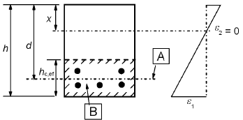
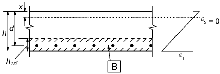
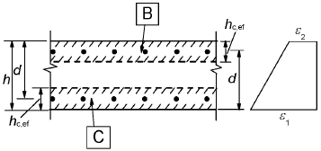
Ac,eff is the effective area of concrete in tension surrounding the reinforcement or prestressing tendons of depth, hc,ef, where hc,ef is the lesser of 2.5(h-d), (h-x)/3 or h/2 (see Figure 7.1).a) Beam

A Inner level of steel centroid B effective tension area, Ac,effb) Slab

B effective tension area, Ac,effc) Member in tension

B effective tension area for upper surface, Act,eff
C effective tension area for lower surface, Acb,effFigure 7.1: Effective tension area (typical cases)
- ξ1 according to Expression (7.5)
- kt is a factor dependent on the duration of the load
kt = 0,6 for short term loading
kt = 0,4 for long term loading
(3) In situations where bonded reinforcenlent is fixed at reasonably close centres within the tension zone (spacing ≤ 5(c+Φ/2)), the maximum final crack spacing may be calculated from Expression (7.11)
where:
- Φ is the bar diameter. Where a mixture of bar diameters is used in a section, an equivalent diameter, Φeq, should be used_ For a section with n1 bars of diameter Φ1 and n2 bars of diameter Φ2, the following expression should be used
- Φeq = (n1·Φ12 + n2·Φ22) / (n1·Φ1 + n2·Φ2)(7.12)
- c: is the cover to the longitudinal reinforcement
- k1: is a coefficient which takes account of the bond properties of the bonded reinforcement:
= 0,8 for high bond bars
= 1,6 for bars with an effectively plain surface (e.g. prestressing tendons) - k2 is a coefficient which takes account of the distribution of strain:
= 0,5 for bending
= 1,0 for pure tension
For cases of eccentric tension or for local areas, intermediate values of k2 should be used which may be calculated from the relation:
k2 = (ε1 + ε2) / (2·ε1)(7.13)
Where ε1 is the greater and ε2 is the lesser tensile strain at the boundaries of the section considered, assessed on the basis of a cracked section
Note: The values of k3 and k4 for use in a Country may be found in its National Annex. The recommended values are 3.4 and 0.425 respectively.
Where the spacing of the bonded reinforcement exceeds 5(c+Φ/2) or where there is no bonded reinforcement within the tension zone, an upper bound to the crack width may be found by assurrling a maximum crack spacing:
(5) For walls subjected to early thermal contraction where the horizontal steel area, As does not fulfil the requirements of 7.3.2 and where the bottom of the wall is restrained by a previously cast base, sr,max may be assumed to be equal to 1,3 times the height of the wall.
Calculation of sections in service with cracking.
Basic assumptions.
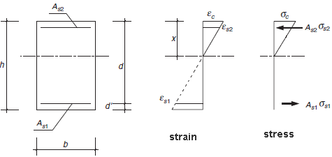
The assumptions made in order to produce the expressions given are as follows:
- The plane of strain remains plane after deformation.
- Perfect bond between concrete and steel.
- Linear behaviour for the compressed concrete.
- The tensile strength of the concrete is ignored.
- Linear behaviour for the steels, under both tension and compression.
Rectangular section.

The equations defining the sectional behaviour are:
(compression: positive sign; tension: negative sign)
- Nk = 1/2·b·x·σc + As2·σs2 + As1·σs1
- Mk = 1/2·b·x·σc·(h/2-x/3) + As2·σs2·(h/2-d') + As1·σs1·(h/2-d)
- σs1 = Es·εs1 = Es·εc·(x-d)/x; |σs1| ≤ k3·fyk
- σs2 = Es·εs2 = Es·εc·(x-d')/x
- σc = Ecm·εc≤ k1· fck
For elements subject to simple bending (Nk=0)
- Depth of the neutral fibre:

- Cracked inertia:
Icr = nAs1(d-X)(d-X/3) + nAs2(X-d')(X/3-d') - Compressive stress in the most compressed concrete fibre
σc = Mk · X / Icr
where n= Es/Ecm; ρ1 = As1/(bd); ρ2 = As2/(bd)


