EC2: Shear strength between soncrete layers
6.2 Shear
6.2.5 Shear at the interface between concrete cast at different times
(1) In addition to the requirements of 6.2.1- 6.2.4 the shear stress at the interface between concrete cast at different times should also satisfy the following:
vEdi is the design value of the shear stress in the interface and is given by:
where:
- β is the ratio of the longitudinal force in the new concrete area and the total longitudinal force either in the compression or tension zone, both calculated for the section considered
- VEd is the transverse shear force
- z is the lever arm of composite section
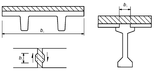
- bi is the width of the interface (see Figure 6.8)

Figure 6.8: Examples of interfaces
vRdi is the design shear resistance at the interface and is given by:
where:
- c and μ are factors which depend on the roughness of the interface (see (2))
- fctd is the design tensile strength
fctd = αct · fctk,0.05 / γc(3.16)where:
- γc is the partial safety factor for concrete,
- αct is a coefficient taking account of long tern1 effects on the tensile strength and of unfavourable effects, resulting from the way the load is applied. Note: The value of αct for use in a Country may be found in its National Annex. The recommended value is 1,0.
- fctk,0.05 = 0.7 · fctm
- σn: stress per unit area caused by the minimum external normal force across the inteliace that can act simultaneously with the shear force, positive for compression, such that σn < 0.6·fcd, and negative for tension. When σn is tensile c·fctd should be taken as 0.
- ρ = As / Ai
- As is the area of reinforcement crossing the interface, including ordinary shear reinforcement (if any), with adequate anchorage at both sides of the interface.
- Ai is the area of the joint
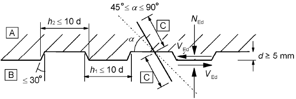
- α is defined in Figure 6.9, and should be limited by 45° ≤ α ≤ 90°
- v is a strength reduction factor (see 6.2.2 (6))
Note: The value v for use in a Country may be found in its National Annex. The recommended value follows from:
v = 0.6·(1-fck/250), (fck in MPa)(6.6N)

A new concrete, B old concrete, C anchorage,
Figure 6.9: Indented construction joint
(2) In the absence of more detailed information surfaces may be classified as very smooth, smooth, rough or indented, with the following examples:
- Very smooth: a surface cast against steel, plastic or specially prepared wooden moulds:
c = 0.025 to 0,10 and μ = 0,5 - Smooth: a slipformed or extruded surface, or a free surface left without further treatment after vibration:
c = 0.20 and μ = 0,6 - Rough: a surface with at least 3 mm roughness at about 40 mm spacing, achieved by raking, exposing of aggregate or other methods giving an equivalent behaviour:
c = 0.40 and μ = 0.7 - Indented: a surface with indentations complying with Figure 6.9:
c = 0.50 and μ = 0,9
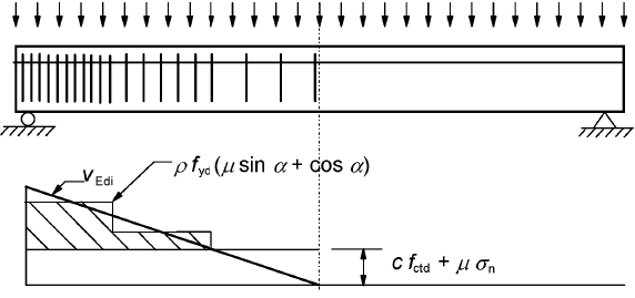
(3) A stepped distribution of the transverse reinforcement may be used, as indicated in Figure 6.10. Where the connection between the two different concretes is ensured by reinforcement (beams with lattice girders), the steel contribution to VRdi may be taken as the resultant of the forces taken from each of the diagonals provided that 45° ≤ α ≤ 135°.
(4) The longitudinal shear resistance of grouted joints between slab or wall elements may be calculated according to 6.2.5 (1). However in cases where the joint can be significantly cracked, c should be taken as 0 for smooth and rough joints and 0,5 for indented joints.
(5) Under fatigue or dynamic loads, the values for c in 6.2.5 (1) should be halved.

Figure 6.10: Shear diagram representing the required interface reinforcement


